|
LTCC Low Temperature Co-fired Ceramic, Thick film printing, Ceramics substrates and LTCC ceramics parts. |
Minicaps
LTCC- Low Temperature Co-fired Ceramic,
Made
in USA |
|||||||||||||||||||||||||||||||||||||||||||||||||
|
LTCC LTCC Low Temperature Co-fired Ceramic Low Temperature Co-fired Ceramic LTCC in 3D Machining ceramics parts LTCC material Cooling tunnels for heat managements Capacitors SLCC Single Layer Ceramic Chip Capacitors MLCC Multi Layer Ceramic Chip Capacitors HVCC High Voltage Ceramic Capacitors
|
LTCC - Low Temperature Co-fired Ceramic, Minicaps offers prototype and manufacturing of LTCC (Low Temperature Co-fired Ceramic), Thick film printing and ceramic substrates. Typical LTCC design rules for LTCC
LTCC Green and fired tape thickness.
LTCC- Low Temperature Co-fired Ceramic parameters LTCC Dielectric constant @1 MHz 7.8 DF (Dissipation Factor) @ 10 MHz 0.15% I R (Insulation Resistance) @ 100 V DC > 1012 Meg ohms Ceramic breakdown Voltage V/25µm > 1000V LTCC Shrinkage X, Y 12.2%, Z 15% Thermal expansion of LTCC (25°C-300°C) 5.8ppm/°C Typical LTCC via diameter is 0.006" via cap 0.009" Line width 0.006", line space 0.006" Cofired inner layer conductor 100% Silver (Ag). Cofired top layer conductor Pd/Ag, Solderable termination, or Gold. Typical Design Rules for LTCC.
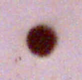
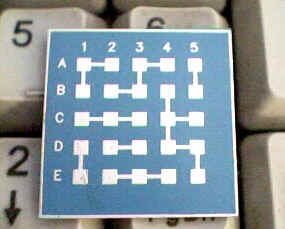
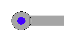
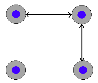
LTCC green tape with 4 mils via (X200) (Recommended 6 mils via) LTCC R1 - 0.006" line and 0.006" space between the lines. LTCC R2 - 0.008" Space -Via cap to line and via cap to via cap (Recommended 0.006" via)
LTCC R3 - 0.006" Via to 0.006" line connection (Recommended 0.006" via)
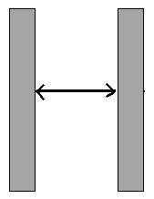
LTCC R4 - 0.008" via cap to via cap (Recommended 0.006" via)
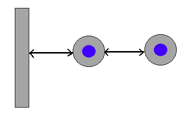
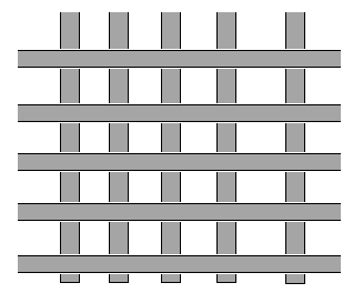
LTCC R5 - Planes, 0.006" grid line and 0.012" space between the line
LTCC R6 - 0.012" space between line to LTCC edge and 0.014" via pad to LTCC edge (Recommended 0.006" via)
go to : LTCC Design Rules, For Engineering assistance in LTCC and information, Please contact Minicaps LTCC (Low Temperature Co-fired Ceramic) : Cost efficiency for high volumes, High packaging density, Reliability, Integrated and embedded passives component (Capacitors Inductors and Resistors) in the LTCC, good dielectric thickness control, high print resolution of conductors, low K dielectric material. The LTCC (Low Temperature Co-fired Ceramic) is a small PCB (printed circuit board), made from multilayer ceramic dielectric tape and screen printing of conductors materials (Silver or Gold). Minicaps offers prototype and manufacturing of LTCC (Low Temperature Co-fired Ceramic), Thick film printing, ceramics substrates, LTCC Ceramic Chip Capacitors, LTCC Multilayer ceramic chip capacitors (MLCC), Single layer ceramic chip capacitors (SLCC), Low Temperature Cofired Ceramic (LTCC) Chip Resistors. For LTCC, Thick film printing, chip Capacitors, chip Resistors, or info, please contact Minicaps Contact, Home, LTCC Low Temperature Co-fired Ceramic, LTCC Design Rules, Low Temperature Co-fired Ceramic LTCC in 3D , Machining ceramics parts LTCC material, Cooling tunnels for heat managements, SLCC Single Layer Ceramic Chip Capacitors, MLCC Multi Layer Ceramic Chip Capacitors, HVCC High Voltage Ceramic Capacitors, Link to LED Products, Link to LTCClab, Link to LEDRunlight, Links page
All rights reserved |
