Minicaps High Tech LTCC ceramics product
LTCC Low Temperature Co-fired Ceramic
Cooling tunnels for heat managements
Machining ceramic parts, LTCC material
Low Temperature Co-fired Ceramic LTCC in 3D
Capacitors
LTCC, SLCC Single Layer Ceramic Chip Capacitors
LTCC, MLCC Multi Layer Ceramic Chip Capacitors
HVCC High Voltage Ceramic Capacitors, LTCC
Resistors
Minicaps offers a variety of ceramic products, Single layer ceramic chip capacitors (SLCC), Ceramic Chip Capacitors, Multilayer ceramic chip capacitors (MLCC), Leaded Capacitors, Chip Resistors, Thick film printing on ceramic substrates, Low Temperature Cofired Ceramic (LTCC) and Multilayer Ceramic Circuits Chip (MCCC). for more information please contact Minicaps. or go to capacitance selector guide
Single
layer ceramic capacitors.
Single layer ceramic chip capacitors (SLCC)
The
capacitors are available in sizes of : 0202 and up to a size of
0909.
The capacitors are
available from 0.2 Pf to 1000 Pf (Go
to: selector guide).
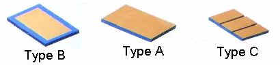
Typical case size and dimension (inches) for type A
|
Case |
Min. |
Max. |
|
C01 |
0.01 |
0.02 |
|
C02 |
0.02 |
0.03 |
|
C03 |
0.03 |
0.04 |
|
C04 |
0.04 |
0.05 |
|
C05 |
0.05 |
0.06 |
|
C06 |
0.06 |
0.07 |
|
C07 |
0.07 |
0.08 |
Other Case sizes and dimension are Available
Ordering Information for Type A, Part # C02 330 K 12
|
C02 |
330 |
K |
12 |
|
Case Size |
Capacitance Code |
Tolerance |
Dielectric Material |
|
C01 to C 07 |
Cap. Pf = Code |
C=+-0.25 Pf |
11 for NPO |
|
|
1.5 Pf = 1R5 |
D=+-0.5 Pf |
12 for X7R |
|
|
33 Pf = 330 |
K=+-10 % |
13 for A, other |
|
|
100 Pf = 101 |
M=+-20 % |
14 for Hi - K |
|
|
220 Pf = 221 |
Z=+80, -20 % |
|
The above part number describes layer Ceramic chip capacitor, With capacitance of 33 Pf. Tolerance +-20%, Size C2, 25x25 mils, 0.025"+-0.005" square and X7R Dielectric material.
Maximum Dissipation Factor (DF) 0.04 @ 100 KHz, typical DF is 0.02@ 100 KHz. Insulation Resistance at 25 Deg. c >10E4 Meg ohms.
For LTCC, Thick film printing, chip Capacitors, chip Resistors, or info, please contact Minicaps
All rights reserved